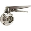
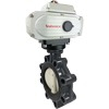
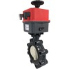
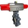
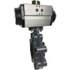
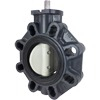
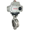
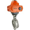
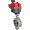
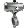
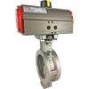
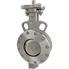
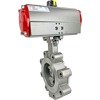
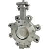
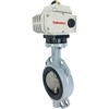
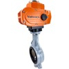
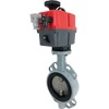
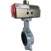
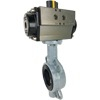
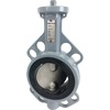
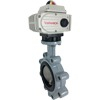
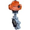
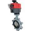
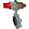
Butterfly Valves
What is a Butterfly Valve
Butterfly valves consist of a valve body with a disc mounted on a shaft to accomplish opening and closing. Sealing is achieved by compressing the disc against the valve seat:
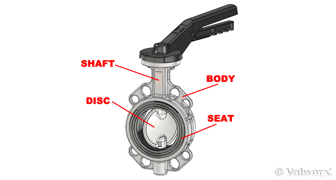
The valve is mounted in-line with the piping, resulting in a compact valve design that can be on/off or throttled. Mounting is typically accomplished utilizing one of three types of end connections. Wafer butterfly valves fit between the connecting pipe flanges and the connecting bolts pass around the valve body through holes at standard locations:
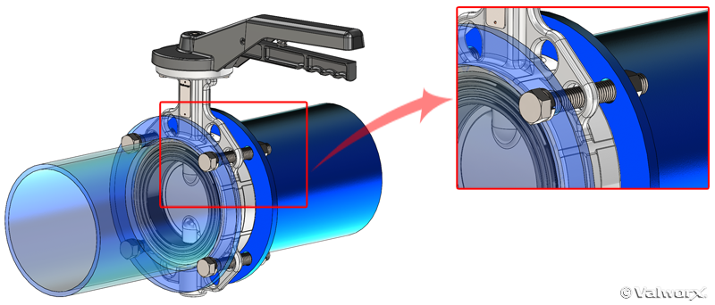
Lug butterfly valves are similar to wafer except the holes are threaded and the valve is secured by bolting the valve from both ends. Lug butterfly valves can also be bolted at the end of the line to be used as an end valve.
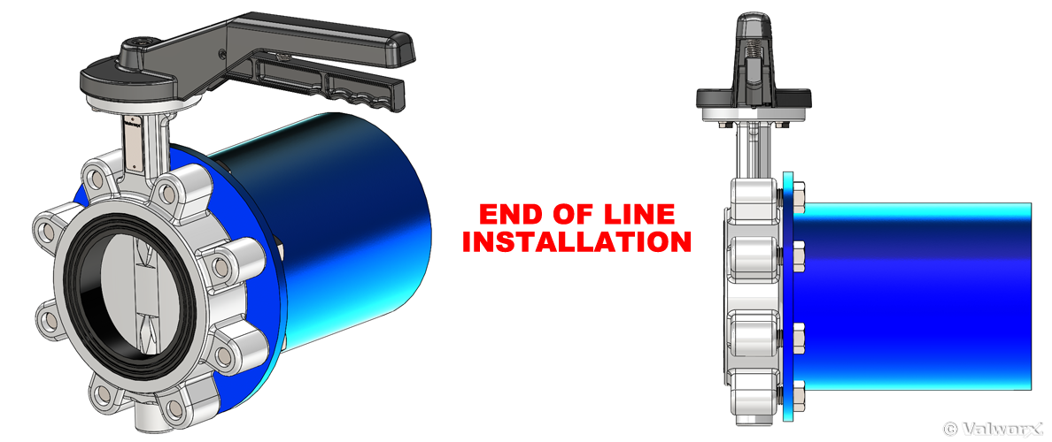
Flange type are bolted into the pipe via standard ANSI flanges on both ends.
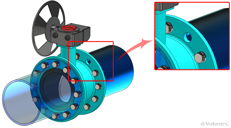
Butterfly valves offer several advantages over comparable gate, globe, and ball valves. Since they use less material than these other types of valves, butterfly valves can be scaled to very large sizes. (Some manufacturers offer butterfly valves in sizes up to 72 inches or more.) They also use less space, and are relatively easy to mount. One of the drawbacks of butterfly valves is that the disc remains in the fluid path reducing flow and increasing pressure drop vs a ball valve.
Butterfly valves have three basic designs. Each has tradeoffs in cost, performance and complexity.
The most common type of butterfly valve employs a concentric design. The disc rotation is aligned with the stem axis and centered along the pipe axis:

Sealing is achieved by the disc compressing against an integral lip molded into the valve seat. The valve seat is made of pliable seal material such as EPDM, FPM or BUNA. Butterfly valves that use a pliable, compressible valve seat for sealing are referred to as resilient seated butterfly valves.
The valve body is typically made of cast iron, ductile iron or PVC. Cast iron is lower cost, has good resistance to vibration but will crack if bent or impacted, and has poor corrosion resistance. Ductile iron will bend upon impact and has much improved corrosion resistance, but costs more than cast iron. PVC is largely non-reactive and therefore a good choice in corrosive environments as well as potable water applications. However, PVC should never be used in compressed gas application because it will shatter upon failure. All Valworx metal butterfly valves are ductile iron butterfly valves, and our PVC butterfly valves are certified to NSF 61 for potable water use.
Machining and fabrication of concentric butterfly valves is fairly simple, and the simplicity of the design along with utilizing low cost materials make concentric butterfly valves a viable low cost solution for many applications including water treatment and crude oil systems.
However, concentric butterfly valves have their limitations. Sealing involves the metal disc rubbing against the valve seat lip until the elastomer is sufficiently compressed. This causes wear on the elastomer, resulting in reduced seal life. Valworx butterfly valves use a wave seal design to reduce this wear:

Even with the wave seal, though, wear is inevitable. In addition, the use of an elastomer limits the useful temperature range and, since sealing relies on compressing the elastomer, limits maximum pressure.
These limitations can be overcome by using all-metal seals instead of elastomers. Unfortunately, rubbing between two metal surfaces will cause one or both to wear quickly, greatly reducing the life of the valve.
The question arises, then, if it is possible to design a butterfly valve so the sealing surfaces do not contact each other until they are completely closed- ie. there is no rubbing of one surface against the other.
Eliminating all sliding contract between the valve disc and the valve seat is the intent behind offset valve design. To understand how offset butterfly valves work, we first need to look at a simpler geometry, a globe valve.
Globe valves use a conical geometry to achieve sealing. Once the cones are in contact, all that is required to maintain the seal is sufficient force:
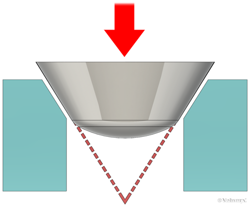
What if this conical sealing principle was applied to a butterfly valve? At first glance, it might look like this:
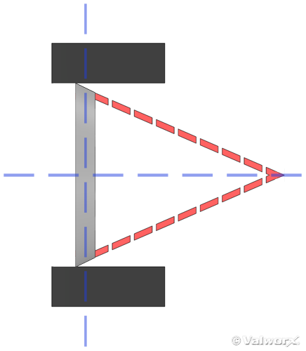
However, a problem arises the moment the disc opens, as the lower disc surface rotates toward the narrowing cone angle and therefore rubs against the valve seat:
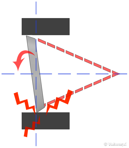
This results in unacceptable wear. Metal-to-metal rubbing can be alleviated to a great extent by aligning the lower disc surface with the cone geometry, i.e. making the lower disc surface perpendicular to the cone angle:
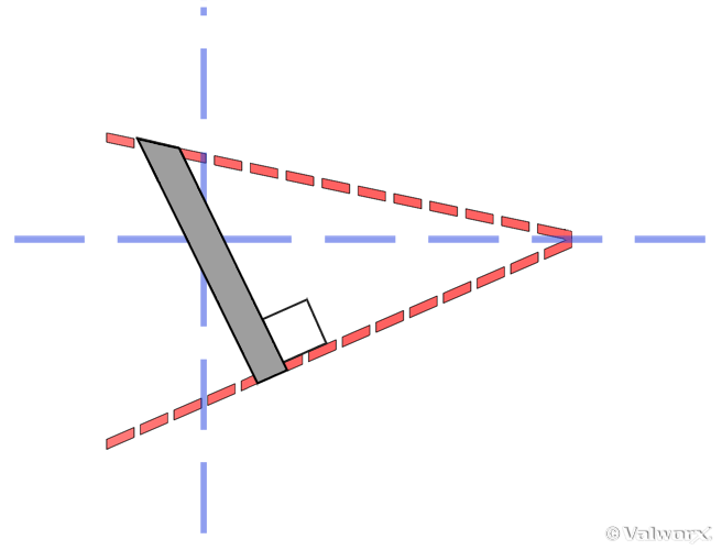
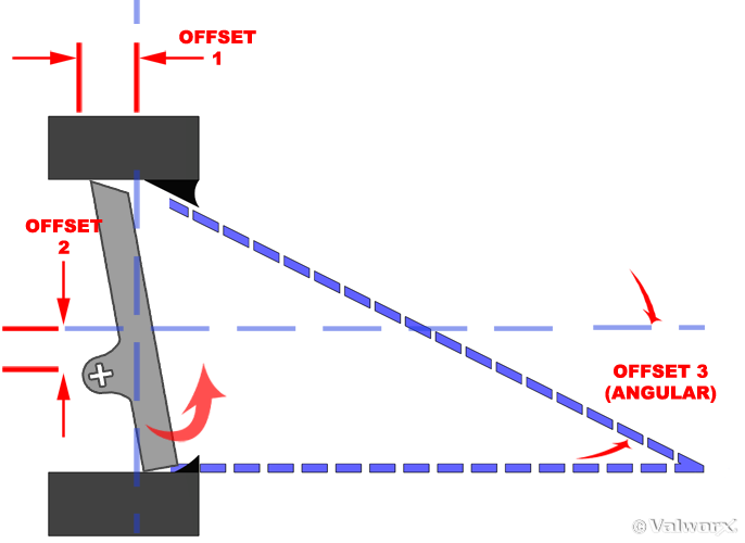
This cone offset is commonly referred to as the third offset (we'll discuss offsets one and two in a moment). Moving this design back to a vertical position, the valve looks like this:
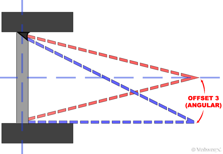
Now when the disc opens, rubbing is greatly minimized...
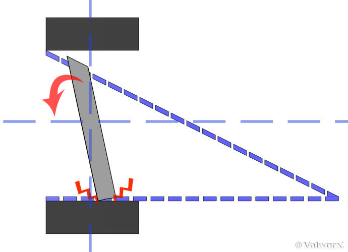
...but not eliminated. Therefore, valve designers employ two other offsets. The rotational axis of the disc is offset from the disc center line (the first offset), and from the pipe center line (the second offset):
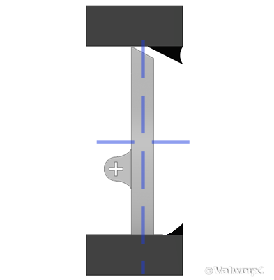
With this geometry the disc no longer rotates concentrically about the disc center line. Instead the offsets act as a cam lever, and the disc swings away from the valve seat instead of rubbing over it:
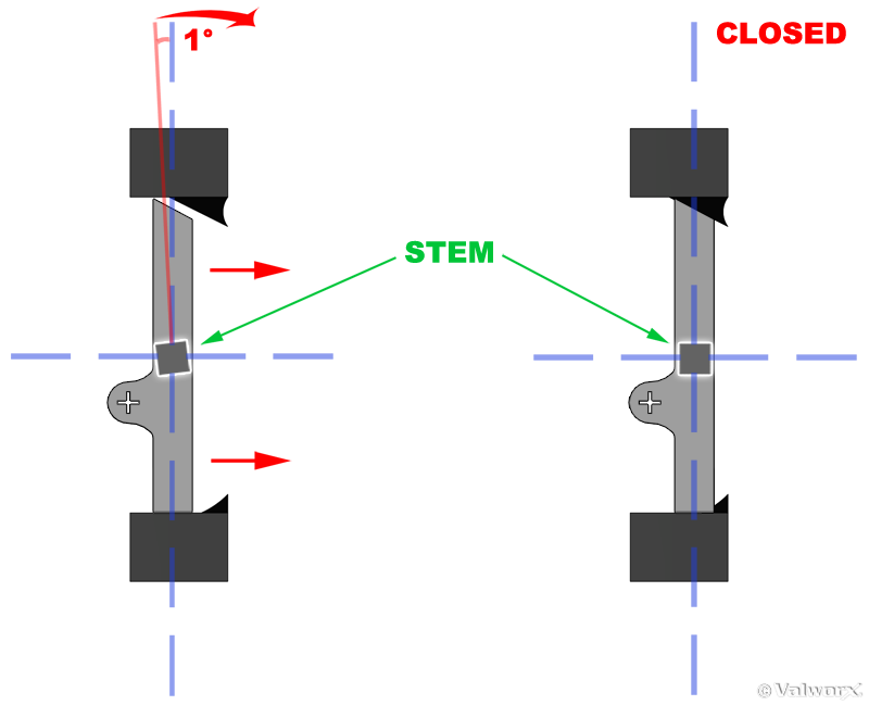
The combination of the camming motion and the cone offset aligns the disc so that during the last one degree or so of stem rotation the disc is perpendicular to the valve seat. The final degree of stem rotation results in the disc moving axially straight onto the valve seat, thus eliminating any relative motion- and therefore rubbing- between the valve disc and valve seat:
This arrangement makes it possible to use metal-to-metal seals, with all the inherent advantages of increased temperature and pressure.
In addition, the third offset acts as a natural stop for the disc. Unlike resilient seated butterfly valves which may travel past the seal lip if too much torque is applied, over torquing triple offset valves (TOV) only results in greater sealing force. To improve valve life and sealing, many manufacturers will use a hardened metal such as stellite for the valve seat material.
These changes greatly improve the capabilities of TOV valves vs their concentric counterparts. TOV valves are used in cryogenic applications (-321F) to very high temperatures (~1200F), with pressures as high as ANSI 2500lbs. In addition, depending on seat and disc material, corrosion and wear resistance are greatly improved.
The major disadvantage for TOV butterfly valves is cost. Offsetting the cone angle means the machining angle for the valve seat and disc varies as a function of circumference. This makes machining much more difficult- and therefore expensive- than a concentric design. If the cone angle was not offset, machining would be easier with correspondingly lower cost.
This raises another question: what happens if we eliminate the cone offset? Can we reduce cost while still improving performance vis a vis concentric butterfly valves?
This is the theory behind double offset valves. A double offset valve still has the camming motion of a TOV, but because the cone is not offset the machining angle of the valve seat is constant. Costs are therefore lower. However, the lower part of the disc rubs against the valve body:
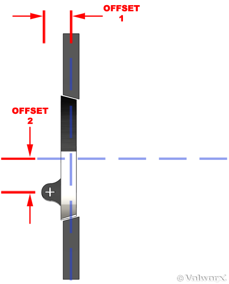
This rubbing is much less than concentric designs, and therefore allows the use of harder materials for the valve seat. While various soft seat materials are still commonly used, sturdier materials such as reinforced Teflon (R-PTFE) with a metal backup ring can also be used. In addition, if the valve is installed so the shaft is upstream the fluid pressure helps close the valve, improving sealing.
The valve body material for double offset butterfly valves is typically ductile iron, although low temperature and sanitary applications use stainless steel. The combination of cheaper materials and easier machining reduces the cost of double offset butterfly valves (commonly referred to as high performance butterfly valves) vs their TOV counterparts, but their additional complexity makes them more expensive than resilient seated butterfly valves.
Thus, high performance (double offset) butterfly valves offer an intermediate solution.
Given their inherent simplicity and scalability, butterfly valves are suitable choices for a myriad of applications. Their performance is further extended by double or triple offset designs, resulting in higher performance although at an increased cost.


